design_coupler can generate a set of dimensions needed for making a directional coupler like that below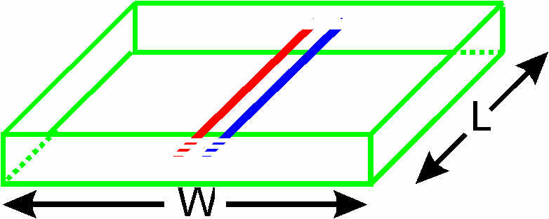
design_coupler. In this example, the % sign is used in front of anything you must type which is what you will probably see when using the csh or tcsh as a shell. It would probably be a $ sign if using the sh or bash shell. Currently a man page does not exist for design_couupler. However, running the program with no arguments gives usage information. To find the odd and even mode impedances and frequency response of a 50 Ohm coupler, covering 130 to 170 MHz, with a coupling coefficient of 30 dB:
% design_coupler 30 130 170

For a 30.000 dB 50.000 Ohm coupler with a length of 0.5000 m,
you need to have an odd-mode impedance Zodd of 48.443 Ohms and
an even mode impedance Zeven of 51.607 Ohms

30.000 dB down <--- ************************** ---> 50.000 Ohm termination

Drive this port --> ************************** ---> 50.000 Ohm termination
                    <-------   0.5000 m ----->

Drive Port 1, coupler out of port 2 and terminate the other ports in Zo
Such a coupler will have the response indicated below.

f = 130.000 MHz   coupling is -30.192 dB down on the main arm
f = 140.000 MHz   coupling is -30.048 dB down on the main arm
f = 150.000 MHz   coupling is -30.000 dB down on the main arm
f = 160.000 MHz   coupling is -30.048 dB down on the main arm
f = 170.000 MHz   coupling is -30.192 dB down on the main arm
Note the frequency response is symmetrical about the centre frequency at 0.192 dB below that wanted. You may wish to redesign this for a coupling coefficient of about 29.9 dB, so the maximum deviation from the ideal 30.0 dB never exceeds 0.1 dB Note the length suggested is 0.5 m (nearly 20") is a quarter wave at the centre frequency of 150 MHz. You might find this a bit too long, so let's specify a length of 0.25 m.
% design_coupler -L 0.25 30 130 170

f = 130.000 MHz   coupling is -31.012 dB down on the main arm
f = 140.000 MHz   coupling is -30.479 dB down on the main arm
f = 150.000 MHz   coupling is -30.000 dB down on the main arm
f = 160.000 MHz   coupling is -29.568 dB down on the main arm
f = 170.000 MHz   coupling is -29.180 dB down on the main arm
What you may notice is that while the coupling to the coupled port is exactly 30 dB below the input power at the centre frequency (150 MHz) it is no longer symmetrical about the centre frequency. Also, deviations from the ideal 30 dB are now much larger, with a maximum error of 1.012 dB Unlike the case when the length is the default quarter wave, there is not much you can do about this, since the deviations occur in both directions.
Now assume you are reasonably happy with the response when the length is 250 mm but would like to see the response at every 2.5 MHz. This can be done using the -s option to design_coupler.
% design_coupler -L 0.25 -s 2.5 30 130 170
f = 130.000 MHz   coupling is -31.012 dB down on the main arm
f = 132.500 MHz   coupling is -30.874 dB down on the main arm
f = 135.000 MHz   coupling is -30.739 dB down on the main arm
f = 137.500 MHz   coupling is -30.607 dB down on the main arm
f = 140.000 MHz   coupling is -30.479 dB down on the main arm
f = 142.500 MHz   coupling is -30.355 dB down on the main arm
f = 145.000 MHz   coupling is -30.233 dB down on the main arm
f = 147.500 MHz   coupling is -30.115 dB down on the main arm
f = 150.000 MHz   coupling is -30.000 dB down on the main arm
f = 152.500 MHz   coupling is -29.888 dB down on the main arm
f = 155.000 MHz   coupling is -29.778 dB down on the main arm
f = 157.500 MHz   coupling is -29.672 dB down on the main arm
f = 160.000 MHz   coupling is -29.568 dB down on the main arm
f = 162.500 MHz   coupling is -29.467 dB down on the main arm
f = 165.000 MHz   coupling is -29.369 dB down on the main arm
f = 167.500 MHz   coupling is -29.273 dB down on the main arm
f = 170.000 MHz   coupling is -29.180 dB down on the main arm
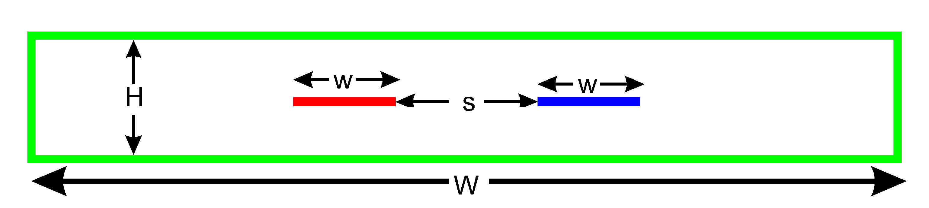
Assuming the performance is acceptable, the dimensions of the coupler can be determined by adding the -d option. This will design a coupler that must look like the structure below. The two inner conductors, which are spaced equally between the top and bottom edges of the outer conductor, must be very thin. These are placed along the length of a box of width W, height H and of a length L determined by the user, which in this case is 250 mm.
|-----------^------------------------------------------------------------------|
|           |                                                                  |
|           |              <---w---><-----s----><--w--->                       |
|           H              ---------            --------                       |
|           |                                                                  |
|           |   Er=1.0 (air)                                                   |
------------v------------------------------------------------------------------
<-----------------------------------------W----------------------------------->
The program reports:
H = 1.0, ; w = 1.44 ; s = 0.44The height of the box H must be small compared to the length L, (perhaps no more than 7% of the length), or 17.5 mm in this case, with a length of 250 mm, otherwise fringing effects will be significant. The width of the structure W should be as large as possible. The program suggests making this 5*H+2*w+s. The 7% and 5*H+2*w+s are educated guesses, rather than exact figures. There is no problem in making the width larger than 5*H+2*w+s. The length L must be kept at 250 mm. The RATIO of the dimensions H, w and s (but not L or W must be kept constant. W just needs to be sufficiently large - it is uncritical.
If you happened to have some 15 mm square brass available, then using that or the side-walls would require that H becomes 15*1.0 = 15 mm, w = 15*1.44 = 21.6 mm and s = 15*0.44 = 6.6 mm
There is no need to compute the above scaling with a calculator, as using The -H option allows one to specify the height H. The program then reports the exact dimensions for the length L, height H, w, s and suggests a minimum width for W. In summary we have:
                   30 dB coupler +1.02 dB / -0.78 dB for 130 to 170 MHz
                   Length L = 250 mm, height H = 15 mm, stripline spacing s
                   = 6.6 mm, stripline width w = 21.6 mm, width W >= 124 mm
By default, design_coupler prints a lot of information to the screen. This can be reduced by the -q option or reduced to only one line with -Q Other options include -Z to change the impedance from the default 50 Ohms and -C to see the fully copyright, Licensing and distribution information
atlc is written and supported by Dr. David Kirkby (G8WRB)